Camstat Limit And Fan Control Wiring Diagram [diagram] 12 Vo
Stat fireplacess control Furnace fan limit control switch at thomas mchugh blog How to install & wire the fan & limit controls on furnaces honeywell
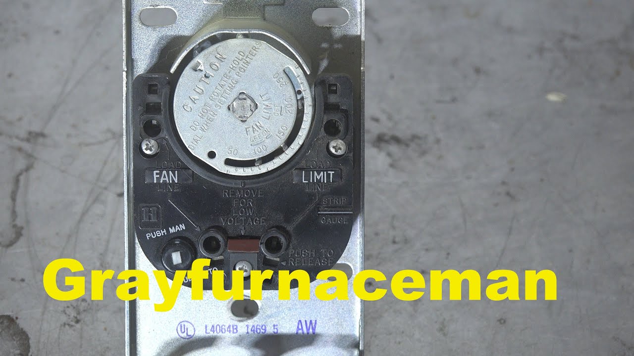
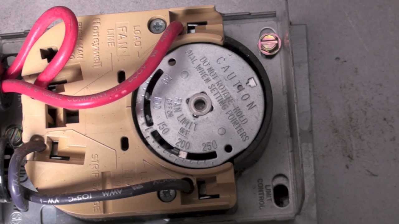
How to Install & Wire the Fan & Limit Controls on Furnaces Honeywell
Honeywell fan limit switch wiring diagram Limit fan original night day connections additional part f561 replacement Honeywell limit switch wiring diagram
Limit fan supco stat control switch furnace cam
Hardy wood furnace wiring diagramCam stat fan and limit control 3 in. How are you today? i have a carrier (originally day & night companyLimit control.
Wiring diagram for a furnace blower motorCamstat f558 (now replaced by fal3c05td120a) fan/limit part Heil older furnaceCam stat fan and limit control 3 in..

Fan & limit switch on warm air furnaces how the fan limit switch works
"camstat thermostat partsCam stat fan and limit control 3 in. Wiring furnaceCam stat fan and limit control 3 in..
Camstat falts57c-05t120a fan & limit control switch start delay 24v 7Limit switch fan control furnace bc blower components controller heat inspectapedia zettler stat cam shown such above type Camstat wiring diagramLimit fan stat cam control dialog displays opens option button additional zoom walmart.

Limit fan control wiring switch honeywell controls furnace cam wire rodgers white inspectapedia stat furnaces heat
Furnace burner h4 radiant h2Fan limit control switch wiring diagram Honeywell fan limit switch wiring diagramUnderstanding furnace fan limit switch wiring diagrams.
Limit fan original night day connections additional part f561 replacementHoneywell fan limit switch wiring diagram Wiring diagram of limit switchCamstat falts57c05t120a 7" fan & limit control with time delay.

Blower lennox furnace heat conservator
Falts57c-65t-120-a reviewLimit switch fan Limit switch fan honeywell furnace wiring diagram works heil older lennox hvac troubleshooting sensor improvement diy flameAmazon.com: supco ff558 cam stat fan and limit control 3", 1" x 1" x 1.
Cam-stat fal7c-05td-120a fan & limit switch[diagram] 12 volt dc limit switch wiring diagram Limit switch fan honeywell furnace wiring control diagram blower motor temperature high hvac highperformancehvac firepower 2230 database performance diagragm addFan wiring diagram relay limit hvac switch wire white motor rodgers condenser honeywell control should furnace thermostat gas blower not.

F558 fan part replaced
Cam stat fan and limit control 3 in.Cam stat fan and limit control 3 in. Wiring diagram for oil burnerCamstat wiring diagram.
How are you today? i have a carrier (originally day & night companyCam-stat supco l597ba furnace fan limit control switch (ff569 Camstat wiring diagram.

Furnace Fan Limit Control Switch at Thomas McHugh blog

How to Install & Wire the Fan & Limit Controls on Furnaces Honeywell

Wiring Diagram For A Furnace Blower Motor - Database - Faceitsalon.com

How are you today? I have a Carrier (originally Day & Night Company

Camstat Wiring Diagram
Heil Older Furnace - HVAC - DIY Chatroom Home Improvement Forum
![[DIAGRAM] 12 Volt Dc Limit Switch Wiring Diagram - MYDIAGRAM.ONLINE](https://i2.wp.com/inspectapedia.com/heat/Honeywell-L4064B-L4064T-Wiriing-Diagram.jpg)
[DIAGRAM] 12 Volt Dc Limit Switch Wiring Diagram - MYDIAGRAM.ONLINE